Our machining centers are also known as:
Click on any term above to learn more...
Hybrid (Parallel-Serial) Layout
Traditional machining centers typically follow a serial layout. To illustrate this, consider the X-Y table in Figure 1:
The upper Y slide is carried by the lower X slide, making the X-Y table the simplest example of a serial layout.
This X-Y table can be classified as a 2-axis serial layout device, defining the X and Y axes accordingly.
Figure 1: X-Y Table
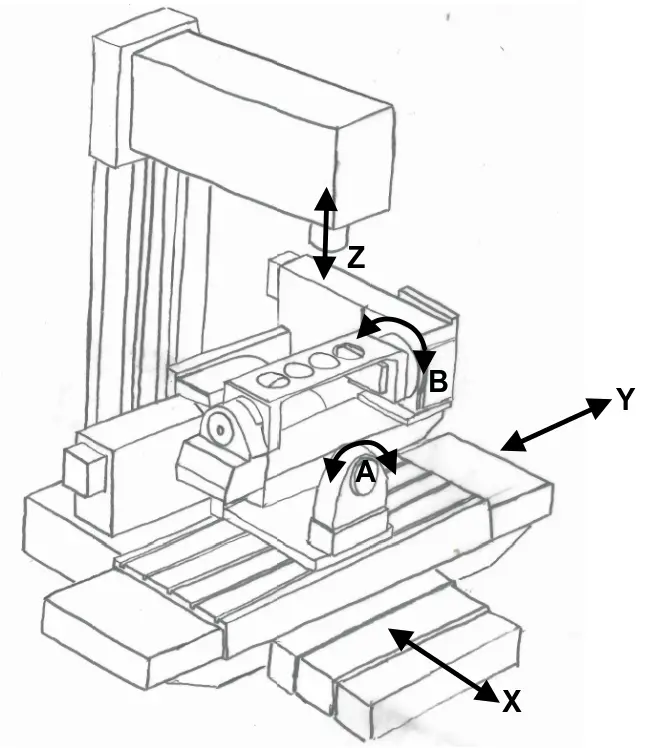
Figure 2: Example of a Traditional 5-Axis (Serial Layout) Machining Center
Example of a Traditional 5-Axis (Serial Layout) Machining Center
Traditional 5-axis machining centers use various serial layouts (as shown in Figure 2). These machines have the advantage of large workspaces. However, they suffer from increased weight, leading to slower operation, and the accumulation of inaccuracies. Speed and accuracy are critical factors in the development of machining centers.
In contrast, parallel layout machine tools were first introduced in 1994, with the Variax from Giddings and Lewis being a notable example. Figure 3 shows a 6-axis parallel layout machine with unparalleled speeds of over 2800 inches/min (66 m/min). Despite its speed, the Variax had a fatal flaw: a very small workspace.
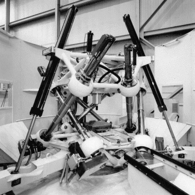
Figure 3: The 6-Axis Parallel Layout Variax by Giddings and Lewis
PMT’s Hybrid (Parallel-Serial) Layout
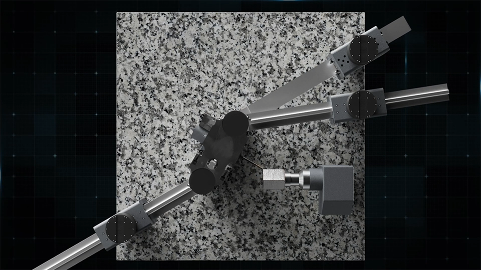
Protea Machine Tools proposes a Hybrid (Parallel-Serial) Layout as shown in Figure 4:
- A 3-legged parallel platform controls movements along the X, Z, and B axes
- The Y axis is stacked in a serial layout on the platform.
- The A axis is a standard rotary axis attached to the machine's steel frame (see Figure 5).
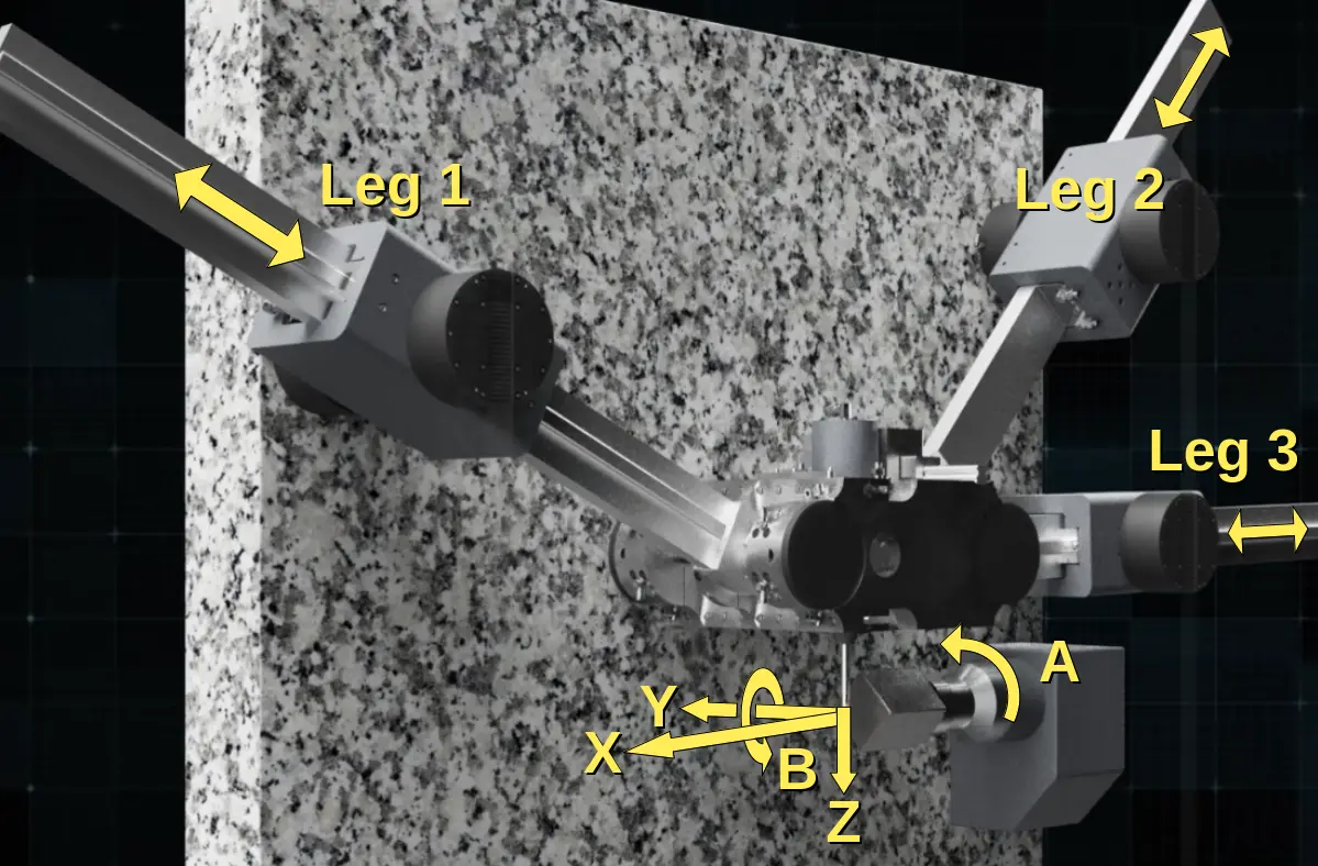
Figure 4: PMT’s 5-Axis Hybrid (Parallel-Serial) Layout
The 3-legged parallel platform moves between two granite surface plates supported by the steel frame, ensuring excellent stiffness in the Y-direction. For clarity, Figure 4 shows only one granite surface plate and omits the steel frame (see Figure 5).
This Hybrid Layout machining center combines the best of both designs:
- Lightning-fast speeds due to the parallel layout of the 3-legged platform.
- Large workspace achieved through:
- The serial layout of the Y and A axes, and
- The machine’s ability to reconfigure itself for different tasks.
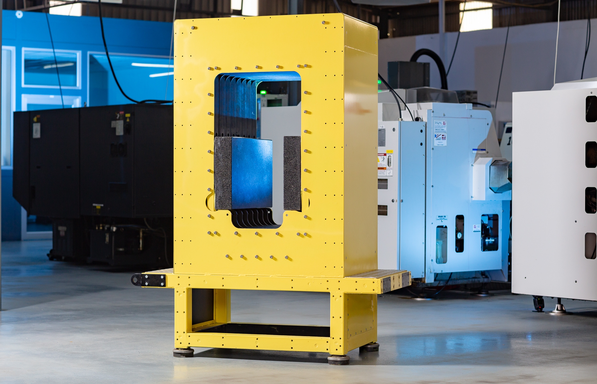
Figure 5: Prototype PMT steel frame supporting two granite surface plates
5-Axis Machining Centers
5-Axis Machining Centers employ advanced automation technology to make complex machining tasks cost-effective. This process involves creating desired shapes by removing excess material from a larger workpiece.
The market size for 5-axis Machining Centers in 2024 was approximately USD 3 billion.
Reconfigurable
The reconfigurability of our Hybrid Parallel-Serial Machining Center is demonstrated in Figures 6 and 7.
Figure 6 shows the cutting tool in a vertical orientation. This setup is defined by the vertical positions of the three pivot points on the 3-legged platform.
Figure 7 illustrates a different configuration, where pivot points 1 and 3 are adjusted to new vertical locations. The yellow overlay in Figure 7 highlights the configuration from Figure 6. In this new setup, the cutting tool is oriented horizontally.
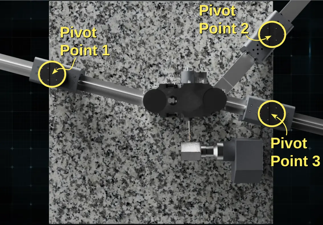
Figure 6: Example Configuration of the 3-Legged Platform
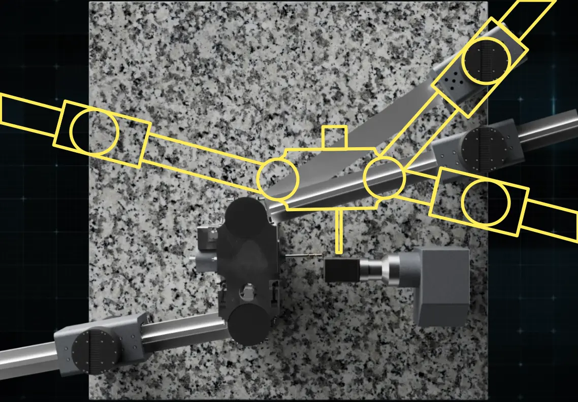
Figure 7: Reconfigured 3-Legged Platform with Horizontal Cutting Tool Orientation